
DESCRIPTION
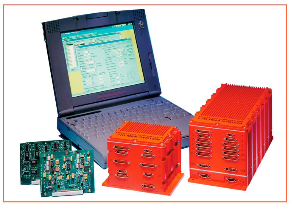
For flight testing airborne vehicles or mobile ground-based testing the Ultra Electronics Herley PCM770 Data Acquisition System is the premier system for acquiring, signal conditioning, and encoding data in severe environments. Versatility, flexibility, and ease-of-use are paramount in this system’s hardware and software design.
The PCM770 is fully compatible with the Master/Slave interface utilized in the smaller, ruggedized PCM880 System. This allows PCM770 and PCM880 Systems to be interchanged to meet any data acquisition requirement. The configuration software for the system supports both PCM770 and 880 Systems concurrently providing one simple interface for both systems.
FEATURES
• Programmable signal conditioning from excitation to PCM output
• Easy to follow Windows® based software and downloadable firmware
• Ruggedized modular housings with EMI/RFI shielding and gasketing
• All housings are environmentally sealed and shielded to meet MIL-STD-461C and MIL-STD-810E
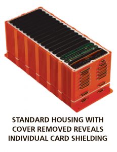
• Metal shields isolate all card slots to minimize noise and crosstalk between cards
• Microminiature D-type Metal (MDM) connectors provide hermetic seals and electromagnetic shields for signal wires and cables
• Remotely programmed and controlled using Windows® based software
• Master Housing can drive up to 15 Slave Housings
• Miniature and Standard size housings provide 4 and 16 slots for plug-in signal conditioners and special function cards
• Plug-in cards are interchange-able and can be installed in any housing
INTRODUCTION: ULTRA ELECTRONICS HERLEY PCM880 DATA ACQUISITION SYSTEM
For flight testing airborne vehicles or mobile ground-based testing the Ultra Electronics Herley PCM770 Data Acquisition System is the premier system for acquiring, signal conditioning, and encoding data in severe environments. Versatility, flexibility, and ease-of-use are paramount in this system’s hardware
and software design. A wide assortment of Signal Conditioners, Bus Monitors, and other special function
cards can be installed in any combination. Signal conditioning is completely programmable from excitation through PCM output.
All operational parameters are set at the system, card, and frame level using easy to follow menus and familiar Windows® commands. Once a unit is installed, programming and calibration are accomplished through remote software, you never have to access the unit again. Real-time data is monitored without the use of a decommutator. The PCM770 System microprocessor can scan the installed hardware, compare it to the user format, and report discrepancies to the system software.
The PCM770 System encoders are designed to provide maximum accuracy of test results in the most severe environments. All housings are environmentally sealed with EMI/RFI shielding and gasketing and meet MIL-STD-810E requirements. To minimize noise and crosstalk, all plug-in slots are individually shielded in the housing. The Standard housing provides 16 card slots and up to 256
signal conditioned channels. Mini-Housings, ideal for small enclosures and rotating platforms, provide 4 card slots with up to 32 signal conditioned channels. A combination of housings can be used in the Master-Slave configuration. The maximum system capacity is 16 housings, each with 16 plug-in cards.
With the versatile and flexible Ultra Electronics Herley PCM770 System, you can easily adapt to changing test specifications and future needs.
SYSTEM HIGHLIGHTS
• Programmable signal conditioning from excitation to PCM output
• Easy to follow Windows® based software and downloadable firmware
• Variable word lengths of 4 to 16 bits per word for maximum bandwidth optimization of digital and analog signals
• Monitor real-time data for system checkout without the use of a decommutator
• Software readback verification of system configuration
• Numerous calibration features for software and hardware interfaces
• Stand-alone or Master-Slave configurations of up to 16 housings
• Standard and Mini-Encoders can be configured as a system Master Encoder
• Standard Housings provide 16 card slots and up to 256 signal conditioned channels
• Mini-Housings provide 4 card slots and up to 32 signal conditioned channels
• Maximum system capacity is 16 housings, each with 16 plug-in cards
• Ruggedized housings with EMI/RFI shielding and gasketing
SOFTWARE FEATURES
The Windows-based software of the PCM770 System is compatible with Windows 3.1, Windows NT, and Windows 95. The system can be controlled by a remote terminal or host computer. System configuration
and hardware configuration information is downloaded directly to the microprocessor. A portable laptop computer can be used in the field during system installation for downloading PCM formats and monitoring system operation. Software includes menu selections for file maintenance, calibration and on-line help.
SYSTEM CONFIGURATION
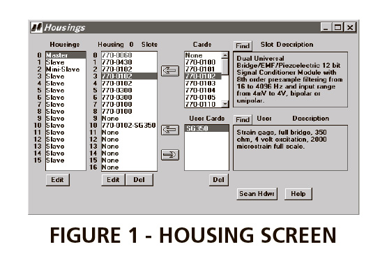
Configuring the system starts with the Housing Screen (Figure 1). Here, the number and type of housings employed by the system are defined. Standard and Mini-Housings are selected as Master or Slave. Within each housing, cards are selected and assigned to a housing slot. Cards may be selected from a list of standard cards or from a list of cards the user has pre-programmed for specific sensors and applications.
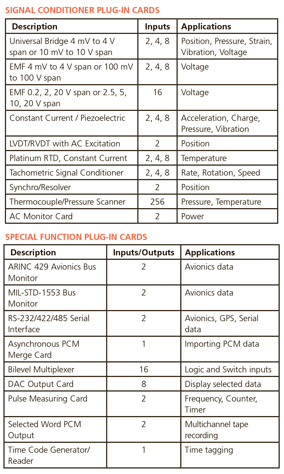
The PCM770 System offers a large selection of plug-in cards. Signal Conditioner cards are available in dual, quad and octal configurations for measuring strain, voltage, acceleration, charge, vibration, position, pressure, power, rate, rotation, speed or temperature. ARINC 429 and MIL-STD-1553 Bus Monitor cards and RS-232/422/485 Serial Interface cards are also available. Other special function cards include Bilevel Multiplexer, DAC Output, Pulse Measuring, and Time Code Generator/Reader cards.
CARD SET-UP
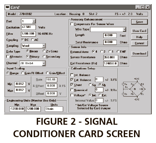
Cards assigned to a housing slot are programmed through specific card configuration screens. Figure 2 shows the set-up for a Dual Universal Signal Conditioner card. From this screen, a user can select the port, set the excitation voltage, pre-sample filter, gain, and offset. Each port is assigned to a channel selected from a list of available channels, or a new channel can be created. Once the user has defined the card set-up, it is saved to the system database. For detailed specifications and capabilities consult individual data sheets or contact the factory.
CHANNEL SET-UP
The Channel set-up screen provides a tabular representation of the PCM frame map and includes card assignments. Information is arranged in columns by channel number and name, word size, frame location, and hardware location. It is easy to add, sort, edit, or delete channels. Each channel can be programmed for normal, super, sub, or random commutation. (Random allows any words in the frame to be linked together as a single data channel.) Channels may be automatically created using the Channel Wizard. Assign a Pre-Label such as VIB, and the Channel Wizard will automatically append a number to create a sequence of channel names such as VIB1, VIB2, VIB3. The Channel Wizard also allows you to select the word and frame numbers you wish to assign to channels in the frame map.
FRAME CONFIGURATION
Two independent frame formats, or master frames, with up to 65,536 words per format, can be stored and selected for use at any time. Frames may be designed with up to 16,384 words per minor frame and
256 minor frames per major frame. Data encoding supports frames with variable word lengths, from 4 to 16 bits including an optional parity bit for data words (Figure 3).
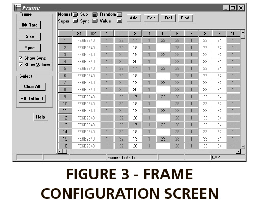
Minor frame synchronization is programmable from 16 to 33 bits, with values entered and displayed in hexadecimal, octal, or binary format. The PCM770 System performs subframe synchronization by frame code complement or subframe ID using one or two subframe ID counters. Each subframe ID counter has an individually programmable count sequence.
CHANNEL MONITOR MODE
View real-time data through the PCM770 System Monitor feature. The system software asynchronously captures two channels of real-time data for viewing and comparison. Figure 4 shows Channel 1 being monitored in Gauge view and Channel 32 is displayed in Waveform view.
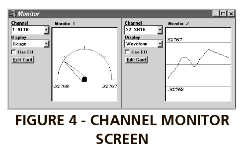
The Monitor feature offers several display options. The Engineering Units option converts raw data to conventional measurements such as degrees, strain, and volts. Waveform shows the data points in scrolling oscillographic format. Gauge provides an easy to read panel meter and Digital lists data values in decimal, hex, or binary format.
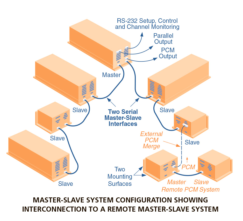
HARDWARE FEATURES
Versatility, flexibility, and modularity are key to the PCM770 System hardware design. One Master Encoder can drive up to 15 Slave Housings. The Master Encoder has two interface connectors allowing
two separate strings of daisy-chained housings. Each string can be up to 10 meters long, for a total system span of 20 meters. To enhance overall system flexibility, housings are available in two sizes. A wide variety of Signal Conditioners, Bus Monitors, and other special function cards can be installed in any housing slot.
SYSTEM COMPONENTS
Standard Housings can be configured as Master or Slave Systems. Standard and Mini-Encoder system components may be ordered as spare parts. Master Systems include the following:
• Housing with 3 or 16 user card slots
• Master Microprocessor
• Power Converter1
• Power Input Mating Connector with wires
• Interface Card
• PCM Output Card
• PCM Output Cable
• RS-232 Computer Interface Cable Slave Systems include the following:
• Housing with 4 or 16 user card slots
• Slave Microprocessor
• Power Converter1
• Power Input Mating Connector with wires
• Master-Slave Interface Cable
• Interface Card
• Master-Slave Interface Terminator
ULTRA ELECTRONICS HERLEY HAS BEEN PROVIDING DATA MEASUREMENT SOLUTIONS FOR
THE SCIENTIFIC TESTING COMMUNITY SINCE 1972. AS THE DEMAND FOR MORE EXTENSIVE
RESEARCH AND TESTING INCREASES, SO DOES THE NEED FOR A SYSTEM THAT IS BOTH
PRECISE AND EASILY PROGRAMMABLE.
THE PCM770 DATA ACQUISITION SYSTEM IS BACKED BY THE QUALITY AND RELIABILITY YOU
HAVE COME TO EXPECT FROM ULTRA ELECTRONICS, HERLEY PRODUCTS. A FLEXIBLE DESIGN,
MODULAR HARDWARE CONFIGURATION, AND PROGRAMMABLE SIGNAL CONDITIONING
MAKE THE PCM770 SYSTEM THE PREMIER PRODUCT FOR SEVERE ENVIRONMENT DATA
ACQUISITION APPLICATIONS.
SYSTEM SPECIFICATIONS
• Configuration: One Master Encoder and up to 15 Slave Housings
• Set-up and Control: Programmed and controlled via RS-232 serial link to a computer with Windows-based software
• Accuracy:
Voltage Gain – within 0.15% of
programmed value at 25°C, with
temperature coefficient of 35 ppm per °C
Voltage Offset – within 0.05% of programmed value
Excitation – within 5 mV of programmed value
• PCM Bit Rate: Programmable selection of internal or external clock.
Internal clock is programmable with 4-digit resolution from 1 kbps to 10 Mbps for NRZ and RNRZ codes (1 kbps to 5 Mbps for other codes).
• PCM Frame Size: Minor frames of up to 16,384 bits. Major frames with up to 256 minor frames, or up to 65,536 total words.
• PCM Word Size: Individually programmable word lengths from 4 to 16 bits (including optional parity
bit)
• PCM Word Order: Programmable for MSB or LSB first
• PCM Word Types: Individually programmable for normal, super, sub, or random commutation
• PCM Word Parity: Programmable as odd, even, or off
• PCM Minor Frame Synchronization: Programmable for frame code complement or subframe ID using one or two programmable subframe counters
• PCM Frame Synchronization: Programmable from 16 to 33 bits
• PCM Output Codes: Conditioned and TTL outputs are independently programmable to the following
PCM codes:
Non-return to zero – NRZ-L
Randomized NRZ – RNRZ-L
Bi-phase – BiØ-L, BiØ-M, BiØ-S
Differential bi-phase – DBiØ-M, DBiØ-S
Delay modulation – DM-M, DM-S
• PCM Conditioned Output: PCM and Bit Clock outputs are 50 ohm driven. PCM output is pre-modulation conditioned to reduce harmonics and is programmable from 0.3 to 3.0 Vpp into a 50 ohm load, or 0.6 to 6.0 Vpp into load of 1,000 ohms or more. Bit Clock output is TTL voltage source.
• PCM TTL Output: TTL driven PCM output with Bit Clock for direct input to a decommutator frame synchronizer
• Parallel Digital Output: TTL output with 16-bit data, word ID, and word clock
POWER REQUIREMENTS
• DC to DC converter power supply accepts input from 11 to 35 volts DC, without manual switching or adjustment. A typical Standard housing with full complement of cards draws about 4 A at 28 V DC.
ENVIRONMENTAL
• Operating Temperature Range:
–40°C to +75°C
• Vibration: MIL-STD-810E; Method
514, Procedure I, Category 5 – Jet
aircraft. Random 10 to 2000 Hz and
sine 5 to 2000 Hz at 10 g’s in three
orthogonal axes
• Shock: MIL-STD-810E; Method
516.4, Procedure I – Functional
shock test for flight test equipment.
20 g’s for 9 to 11 ms in both directions along three orthogonal axes
• Altitude: MIL-STD-810E; Method
520, Procedure II – Flight test
support. Operation from –40°C to
+70°C at 70,000 ft.
• Salt Fog: MIL-STD-810E; Method
509.3. Expose 48 hours at 35°C
• Humidity: RTCA/DO-160C; Section
6, Category A. Expose 48 hours at
95% minimum humidity
• Power: MIL-STD-704E; Paragraph
5.3. (40 V DC max. input)
• EMI/RFI: MIL-STD-461C; Requirements CE03, CE07, CS01, CS02,
CS06, RE02, RS02
PHYSICAL
• Standard Housing Weight: 12 pounds (5.4 kg) with full complement of cards
Height: 4.93 inches (125 mm)
Width: 4.84 inches (123 mm)
Length: 11.90 inches (302 mm)
• Miniature Housing Weight: Under 3 pounds (1.3 kg) with full complement of cards
Height: 4.00 inches (102 mm)
Width: 5.8 inches (147 mm)
Length: 4.00 inches (102 mm)
• Miniature Power System
Weight: Under 3 pounds (1.3 kg)
Height: 4.00 inches (102 mm)
Width: 5.8 inches (147 mm)Length:
4.00 inches (102 mm)
• Note: Specifications subject to change without notice.